Category: Technical Deep Dives

  • How Car Cooling Systems Work to Prevent Overheating

    How Car Cooling Systems Work to Prevent Overheating

    An effective cooling system overview is essential to keep your engine operating within safe temperature ranges. Without proper engine cooling, internal components can warp, seize, or suffer premature wear. In this guide, we’ll explore how the primary components—including the radiator function, water pump, thermostat, and hoses—work together to regulate temperature and protect your vehicle’s heart.

    1. Cooling System Overview

    The car’s cooling system is a closed-loop network that circulates a water‑based coolant through the engine, absorbing and dissipating heat. Key elements include:

    • Coolant: A mixture of water and antifreeze that transfers heat efficiently and resists freezing.
    • Water Pump: Drives coolant flow through the circuit.
    • Thermostat: Regulates coolant flow based on temperature.
    • Radiator: Releases heat from the coolant into the surrounding air.
    • Hoses & Passages: Connect all components and guide coolant through the engine block and cylinder head.
    • Cooling Fans: Pull air through the radiator when vehicle speed alone isn’t enough.

    By continuously cycling coolant through hot and cool zones, the system maintains engine temperatures typically between 180 °F and 220 °F (82 °C–104 °C).

    2. Radiator Function

    The radiator function is to discard heat absorbed by the coolant. As hot coolant enters the radiator’s top inlet, it travels through a network of thin tubes and fins:

    • Tubes: Carry coolant down through the core.
    • Fins: Expand surface area to accelerate heat transfer to passing air.

    Airflow—either from forward motion or electric fans—draws heat away, cooling the fluid before it returns to the pump. A well‑maintained radiator core ensures efficient heat rejection and prevents hotspots in the engine.

    Radiator Cap & Pressure

    The radiator cap maintains system pressure, raising the coolant’s boiling point. At around 15 psi above atmospheric pressure, the boiling point can exceed 265 °F (129 °C). This keeps the coolant liquid under high temperatures, ensuring uninterrupted circulation.

    3. Coolant Flow & Water Pump

    The water pump is the mechanical heart of the cooling loop. Driven by a belt or electric motor, it pushes cooled fluid from the radiator into the engine’s passages:

    1. Coolant enters the front of the engine block, absorbing heat around cylinders.
    2. It then flows upward into the cylinder head, cooling combustion chambers and valves.
    3. Hot coolant exits the head and heads back to the radiator for heat rejection.

    Consistent flow prevents localized overheating and maintains uniform temperatures across all engine parts.

    4. Thermostat Operation

    The thermostat is a temperature-sensitive valve placed between the engine outlet and radiator inlet. When the engine is cold, the thermostat remains closed, allowing coolant to circulate only through a bypass loop. This speeds up warm‑up and ensures efficient combustion. Once the coolant reaches approximately 195 °F (90 °C), the valve opens, directing fluid through the radiator core for cooling.

    5. Cooling Fans & Auxiliary Components

    At low speeds or idle, airflow through the radiator may be insufficient. Electric or belt‑driven fans engage based on coolant temperature or A/C usage, forcing air through the core. Additional parts supporting engine cooling include:

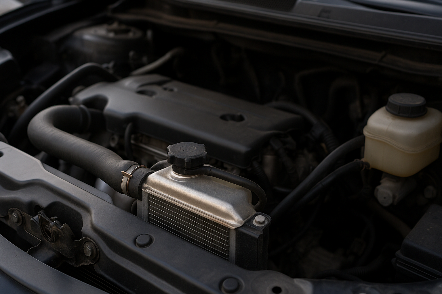
    • Overflow Reservoir: Captures expanding coolant and returns it as temperatures drop.
    • Hoses & Clamps: Flexible connections that withstand heat and pressure.
    • Heat Exchanger / Heater Core: Transfers engine heat to the cabin for defrost and HVAC.

    6. Maintenance Tips

    To keep your cooling system performing optimally:

    • Inspect & Replace Coolant: Change every 2–5 years per manufacturer recommendations.
    • Check for Leaks: Examine hoses, radiator seams, and pump seals regularly.
    • Test Thermostat & Cap: Replace if you notice slow warm‑up, overheating, or frequent boil‑overs.
    • Clean Radiator Fins: Remove debris to maintain unobstructed airflow.
    • Monitor Fan Operation: Ensure fans engage when the engine is hot or A/C is on.

    Conclusion

    A robust cooling system overview reveals how interdependent components—from the radiator function to the water pump and thermostat—collaborate to deliver reliable engine cooling. Regular inspections, timely coolant changes, and attention to hoses and fans will help your vehicle resist overheating and extend engine life, ensuring dependable performance in all conditions.

  • ABS & Traction Control: How Safety Systems Keep You on the Road

    ABS & Traction Control: How Safety Systems Keep You on the Road

    Modern vehicles come equipped with advanced vehicle safety features designed to help drivers maintain control in slippery or emergency situations. Two of the most important systems are the Anti‑Lock Braking System (ABS) and traction control. In this guide, we’ll explain how each system works, explore their benefits, and show why understanding ABS explained can make you a safer driver.

    1. What Is ABS? ABS Explained

    The Anti‑Lock Braking System prevents your wheels from locking up under heavy braking, allowing you to steer around obstacles instead of skidding straight ahead. Here’s how it works:

    • Wheel Speed Sensors: Each wheel has a sensor that monitors its rotational speed.
    • Electronic Control Unit (ECU): Detects when a wheel is about to lock by comparing wheel speeds.
    • Hydraulic Modulator: Rapidly pulses brake pressure three to fifteen times per second to maintain traction.

    By modulating brake pressure, ABS keeps the tire’s contact patch from sliding uncontrollably, reducing stopping distances on wet or icy roads and enabling you to maintain steering control.

    2. How Traction Control Works

    Traction control complements ABS by preventing wheel spin during acceleration. It uses many of the same wheel‑speed sensors and ECU logic:

    • Detection: Sensors notice when a drive wheel spins faster than the others, indicating a loss of grip.
    • Intervention: The ECU reduces engine torque—by retarding ignition timing or cutting fuel—and/or applies brake pressure to the spinning wheel.
    • Restoration: Once traction returns, normal power delivery resumes.

    Traction control helps you launch more smoothly on slippery surfaces, such as wet pavement or loose gravel, reducing wheel spin and improving directional stability.

    3. ABS vs. Traction Control: Key Differences

    While both systems rely on wheel‑speed sensors, their purposes differ:

    • ABS: Activates during braking to prevent wheel lock‑up and maintain steering control.
    • Traction Control: Activates during acceleration to prevent wheel spin and maintain forward momentum.

    Together, they form a coordinated safety network, with ABS managing deceleration and traction control managing acceleration, both leveraging the same brake‑hydraulic hardware and ECU intelligence.

    4. Benefits of ABS & Traction Control

    Understanding these vehicle safety features highlights several real‑world advantages:

    • Shorter Stopping Distances: ABS can reduce braking distance by up to 20% on wet roads.
    • Improved Steering Control: Prevents skidding, allowing drivers to steer around hazards while braking.
    • Smoother Acceleration: Traction control minimizes wheel spin, especially on ice or gravel.
    • Reduced Tire Wear: Controlled braking and acceleration reduce flat spots and uneven wear.
    • Enhanced Confidence: Drivers feel more secure knowing their car will help modulate braking and power delivery.

    5. When to Rely on These Systems

    While ABS and traction control intervene automatically, it’s helpful to know when they engage:

    • Wet or Icy Roads: Sudden braking or hard acceleration will trigger ABS and traction control most effectively.
    • Loose Surfaces: Gravel, sand, or snow often cause wheel slip, where traction control shines.
    • Emergency Maneuvers: Panic stops will activate ABS, helping you steer around unexpected obstacles.

    Note that these systems improve safety but do not replace proper driving techniques—maintaining safe following distances and adjusting speed for conditions remain essential.

    6. Maintenance and Troubleshooting

    To ensure your ABS and traction control continue to function:

    • Inspect Wheel Sensors: Clean sensors and wiring regularly; replace damaged components.
    • Check Brake Fluid: Maintain proper levels and change fluid according to manufacturer guidelines.
    • Monitor Warning Lights: An illuminated ABS or traction control light indicates a fault—have it diagnosed and repaired promptly.
    • Keep Tires in Good Condition: Match tire sizes and pressure on all wheels to ensure sensor accuracy.

    Conclusion

    By understanding ABS explained and the workings of traction control, you’ll appreciate how these vehicle safety features combine to keep you in command—whether you’re braking on a rain‑slick highway or accelerating out of a snowy driveway. Regular maintenance and respect for road conditions will help these systems perform at their best, enhancing safety and confidence on every drive.

  • The Science of Fuel Injection: How Modern Engines Stay Efficient

    The Science of Fuel Injection: How Modern Engines Stay Efficient

    Modern internal combustion engines achieve remarkable engine efficiency thanks to advances in fuel injection systems. Gone are the days of simple carburetors—today’s electronic fuel injection (EFI) precisely meters and times fuel delivery to each cylinder, optimizing power output and reducing emissions. In this article, we’ll explore how EFI works, its key components, and why it’s essential for efficiency and performance.

    1. Evolution from Carburetors to EFI

    Historically, carburetors mixed air and fuel based on vacuum pressure—an inherently imprecise method. In contrast, EFI uses sensors, an electronic control unit (ECU), and injectors to deliver the exact amount of fuel needed at any given moment. This transition has led to:

    • Sharper throttle response
    • Improved fuel economy
    • Lower tailpipe emissions
    • Better cold‑start performance

    2. Key Components of an Electronic Fuel Injection System

    An EFI system consists of several interconnected parts that work together to maintain optimal air‑fuel ratios (typically around 14.7:1 for gasoline engines).

    2.1 Engine Control Unit (ECU)

    • Central “brain” that processes sensor inputs.
    • Runs fuel‑mapping software to determine injector pulse width.
    • Adjusts ignition timing for robust performance and efficiency.

    2.2 Fuel Injectors

    • High‑precision nozzles that spray atomized fuel directly into the intake port or combustion chamber.
    • Controlled by the ECU as rapid on/off pulses, typically measured in milliseconds.
    • Ensure fine atomization for complete combustion.

    2.3 Sensors

    Modern EFI relies on multiple sensors to monitor engine and environmental conditions:

    • Mass Air Flow (MAF) Sensor: Measures incoming air volume.
    • Manifold Absolute Pressure (MAP) Sensor: Tracks engine load.
    • Oxygen (O₂) Sensor: Monitors exhaust composition to fine‑tune air‑fuel mix.
    • Engine Coolant Temperature (ECT) Sensor: Adjusts fueling during warm‑up.
    • Throttle Position Sensor (TPS): Detects driver’s throttle input.

    3. How EFI Delivers Engine Efficiency

    The primary goal of EFI is to maintain the stoichiometric air‑fuel ratio, where combustion is most complete. Here’s how EFI contributes to efficiency:

    3.1 Precise Fuel Metering

    By varying injector pulse width based on real‑time sensor data, EFI ensures just enough fuel is injected for combustion—no more, no less. This precision minimizes wasted fuel and reduces unburned hydrocarbons.

    3.2 Adaptive Learning

    Many modern ECUs feature adaptive algorithms that learn engine behavior over time. They compensate for changes such as aging sensors, fuel quality variations, and altitude differences, continually refining fuel maps for consistent engine efficiency.

    3.3 Multi‑Point vs. Direct Injection

    EFI has evolved into two main architectures:

    • Multi‑Point Fuel Injection (MPFI): Injectors spray fuel into each intake port upstream of the intake valve.
    • Gasoline Direct Injection (GDI): Injectors deliver fuel directly into the combustion chamber under high pressure, allowing stratified charge and lean‑burn operation for enhanced efficiency.

    4. Benefits Beyond Mileage

    While improved gas mileage is a key advantage, EFI offers additional benefits:

    • Lower Emissions: Precise combustion reduces NOₓ, CO, and unburned hydrocarbons.
    • Better Drivability: Smooth idle, quick starts, and linear throttle response.
    • Enhanced Durability: Cleaner combustion leaves fewer deposits on valves and pistons.

    5. Maintaining Your EFI System

    To ensure continued performance and engine efficiency, follow these maintenance tips:

    • Replace Fuel Filters: Prevent injector clogging and preserve flow rates.
    • Use Quality Fuel: Detergent additives help keep injectors and intake ports clean.
    • Inspect Sensors: Clean or replace faulty MAF/O₂ sensors to maintain accurate readings.
    • Periodic ECU Updates: Some manufacturers release software updates for optimized fuel maps.

    Conclusion

    The fuel injection system—particularly electronic fuel injection—is a cornerstone of modern automotive design, balancing power and efficiency through precise metering and advanced controls. By understanding how EFI works and caring for its components, you’ll enjoy smoother performance, better fuel economy, and cleaner emissions, ensuring your engine stays healthy and efficient for years to come.

  • EV Powertrain 101: Motor, Inverter, and Battery Basics

    EV Powertrain 101: Motor, Inverter, and Battery Basics

    Electric vehicles rely on a fundamentally different drivetrain than traditional gasoline cars. The heart of an EV is its EV powertrain, which consists primarily of the electric motor, inverter, and battery pack. Understanding the roles and interactions of these components—electric motor basics and battery fundamentals—is key to appreciating how EVs achieve instant torque, high efficiency, and zero tailpipe emissions.

    1. The EV Powertrain Overview

    An EV powertrain replaces the internal combustion engine, transmission, and fuel system with three main elements:

    • Electric Motor: Converts electrical energy into mechanical rotation to drive the wheels.
    • Inverter: Manages power flow by converting DC battery voltage into AC for the motor, and vice versa during regenerative braking.
    • Battery Pack: Stores electrical energy in a series of cells and delivers it on demand to the inverter and motor.

    Unlike multi‑gear transmissions in ICE vehicles, many EVs use a single reduction gear, relying on the motor’s wide torque band for acceleration and cruising.

    2. Electric Motor Basics

    The electric motor is the centerpiece of EV propulsion. There are several common types:

    • Permanent Magnet Synchronous Motor (PMSM): Uses rare-earth magnets on the rotor to create a constant magnetic field, offering high efficiency and power density.
    • Induction Motor: Relies on electromagnetic induction to generate rotor currents; robust and inexpensive but slightly less efficient at low loads.
    • Switched Reluctance Motor (SRM): Utilizes variable reluctance in the magnetic circuit; emerging for its simplicity and high-temperature tolerance.

    In operation, the inverter supplies three-phase AC currents to the stator windings. These currents create a rotating magnetic field, which interacts with the rotor’s field (permanent magnets or induced currents) to produce torque. The motor’s instantaneous torque—available from zero RPM—delivers the brisk acceleration EVs are known for.

    3. Inverter Function and Control

    The inverter serves as the brain of the EV powertrain. Key roles include:

    • DC-to-AC Conversion: Transforms the battery’s DC voltage into variable-frequency AC to control motor speed and torque.
    • Regenerative Braking: Captures kinetic energy during deceleration by reversing the motor’s operation, converting mechanical energy back into electrical energy and storing it in the battery.
    • Thermal Management: Monitors and manages its own temperature to avoid overheating under high loads.

    Modern inverters use high‑speed semiconductor switches (IGBTs or SiC MOSFETs) and sophisticated pulse‑width modulation (PWM) algorithms to deliver smooth torque control, high efficiency, and precise response.

    4. Battery Fundamentals

    The battery pack is the EV’s fuel tank. Understanding battery fundamentals involves:

    • Cell Chemistry: Most EVs use lithium‑ion cells—variations include NMC (nickel manganese cobalt), LFP (lithium iron phosphate), and NCA (nickel cobalt aluminum)—each balancing energy density, cost, and longevity.
    • Module & Pack Design: Cells are grouped into modules, which are assembled into a pack. The pack includes structural support, cooling plates, and wiring harnesses.
    • Battery Management System (BMS): Monitors cell voltages, temperatures, and currents, ensuring balanced charging/discharging and protecting against over‑charge or over‑discharge.
    • Thermal Control: Liquid or air cooling maintains optimal cell temperature (often 20–40 °C) to preserve performance and lifespan.

    Pack capacity, measured in kilowatt‑hours (kWh), directly influences driving range. Efficient thermal and BMS strategies help maximize usable capacity and extend battery life.

    5. Integration & Efficiency Considerations

    To maximize overall efficiency, EV designers integrate motor, inverter, and battery into a cohesive system:

    • Power Electronics Co‑Location: Placing the inverter close to the motor reduces high‑voltage wiring losses.
    • Regenerative Braking Tuning: Balances energy recapture with drivability, modulating how aggressively the motor switches to generator mode.
    • Thermal Synergy: Shared cooling loops for motor, inverter, and battery minimize system complexity and improve thermal stability.

    Careful system integration allows leading EVs to achieve well over 90 percent drivetrain efficiency—far surpassing most internal combustion vehicles.

    Conclusion

    Mastering the electric motor basics, inverter control, and battery fundamentals provides a solid foundation for understanding any EV. The EV powertrain blends these technologies to deliver quiet, efficient, and high‑torque propulsion. As innovations in motor design, power electronics, and battery chemistry continue, future EVs will only become more capable, affordable, and sustainable.

  • Understanding OBD‑II Codes and What They Mean

    Understanding OBD‑II Codes and What They Mean

    If your dashboard’s “Check Engine” light ever comes on, grabbing an OBD‑II scanner is the first step to diagnosing the problem. This OBD‑II guide will help you decode check engine codes—officially known as diagnostic trouble codes (DTCs)—so you can understand what your vehicle’s computer is telling you and decide your next move.

    1. What Is OBD‑II?

    OBD‑II (On‑Board Diagnostics, Second Generation) is a standardized system in vehicles manufactured since 1996 that monitors engine and emissions systems. When the powertrain control module (PCM) detects a fault—be it a loose gas cap or a misfiring cylinder—it stores a corresponding DTC and illuminates the “Check Engine” light.

    System Monitored by OBD‑II

    • Engine misfires and ignition faults
    • Fuel system and mixture control
    • Exhaust gas recirculation (EGR) and catalytic converter efficiency
    • Evaporative emissions (EVAP) leaks
    • Sensors such as oxygen (O₂), mass air flow (MAF), and manifold absolute pressure (MAP)

    2. Anatomy of a Diagnostic Trouble Code

    Each DTC follows a five‑character format: [Letter][Digit][Digit][Digit][Digit].

    • Letter: Indicates system
      • P: Powertrain (engine and transmission)
      • B: Body (airbags, climate control)
      • C: Chassis (ABS, suspension)
      • U: Network & vehicle integration
    • First Digit:
      • 0 = Standard (SAE defined)
      • 1 = Manufacturer‑specific
    • Second Digit: Subsystem
      • P0xxx = Fuel & air metering
      • P2xxx = Injector circuit
      • P3xxx = Ignition system
      • P4xxx = Auxiliary emissions controls
      • P5xxx = Vehicle speed controls & idle control
      • P6xxx = Computer output circuits
      • P7xxx–P8xxx = Transmission
    • Last Two Digits: Specific fault identifier (00–99)

    3. Common Check Engine Codes

    Here are a few frequently encountered OBD‑II codes and what they typically indicate:

    • P0171 / P0174: System Too Lean – Bank 1/2 (often due to vacuum leaks or faulty MAF sensor)
    • P0300: Random/Multiple Cylinder Misfire Detected (ignition, injector, or compression issue)
    • P0420: Catalyst System Efficiency Below Threshold (catalytic converter or O₂ sensor problem)
    • P0442: Evaporative Emission Control System Leak Detected (small EVAP leak, possibly a loose gas cap)
    • P0128: Coolant Thermostat Below Regulating Temperature (stuck open thermostat)

    4. How to Read and Interpret Codes

    Follow these steps in your DIY OBD‑II guide workflow:

    1. Connect a Scanner: Plug your OBD‑II reader into the port—usually under the dashboard.
    2. Power On: Turn the ignition to the “ON” position without starting the engine.
    3. Retrieve Codes: Follow prompts on the scanner to “Read Codes.” Write down all stored codes.
    4. Look Up Definitions: Use your scanner’s database or an online DTC list to find code meanings.
    5. Check Freeze Frame Data: Some scanners display the engine conditions when the fault occurred (temperature, load, speed).
    6. Clear Codes & Test Drive: After repairs, clear codes and drive to ensure the light stays off and no new codes appear.

    5. Next Steps After Reading Codes

    Once you have your diagnostic trouble codes, proceed as follows:

    • Verify the Fault: Confirm the issue by visual inspection—check wiring, hoses, and connectors related to the code.
    • Perform Repairs or Replacements: Replace faulty sensors, tighten gas caps, or address leaks as indicated by the code.
    • Reset and Monitor: Clear codes and run another scan after a brief drive to verify the solution.
    • Seek Professional Help: If codes persist or repair is complex (e.g., internal transmission faults), consult a qualified mechanic.

    Conclusion

    Grasping the basics of the OBD‑II guide and knowing how to check engine codes empowers you to diagnose many common issues yourself. By interpreting diagnostic trouble codes accurately and following a logical repair process, you’ll save time and money—plus gain confidence in maintaining your vehicle’s health.

  • How Turbochargers Work: Boosting Engine Power Explained

    How Turbochargers Work: Boosting Engine Power Explained

    If you’ve ever wondered how small engines can produce surprising amounts of power, the secret often lies in the turbocharger. By harnessing exhaust gases to compress incoming air, a turbocharger delivers greater oxygen density into the combustion chamber, resulting in a significant engine boost. In this guide, we’ll cover the turbocharger working principle, break down the key turbo basics, and explain why turbocharged engines outperform their naturally aspirated counterparts.

    1. The Turbocharger Working Principle

    At its core, a turbocharger is a forced-induction device that increases the amount of air—and therefore fuel—that an engine can burn. It consists of two main sections:

    • Turbine Side: Driven by hot exhaust gases exiting the engine.
    • Compressor Side: Draws in and compresses ambient air before feeding it into the intake manifold.

    The two sides are linked by a central shaft. As exhaust gases spin the turbine wheel, the connected compressor wheel spins at high speed—often tens of thousands of RPM—compressing incoming air. Denser air allows for more fuel to be added, creating a more powerful combustion event and delivering the sought-after engine boost.

    Key Components

    • Turbine Housing: Channels exhaust gases onto the turbine wheel.
    • Compressor Housing: Directs fresh air through the compressor wheel and into the engine.
    • Center Housing & Rotating Assembly (CHRA): Houses bearings and lubricating passages for the shaft.
    • Wastegate: Regulates exhaust flow to control boost pressure and prevent over-boost.

    2. Turbo Basics: How It Boosts Power

    Understanding a turbocharger’s benefit requires a look at air density and combustion. Naturally aspirated engines rely on atmospheric pressure to fill cylinders, but a turbocharger increases intake pressure above atmospheric levels—known as “boost.”

    Boost and Air Density

    When the compressor wheel spins, it draws in ambient air and forces it into the intake manifold at higher pressure. This compressed air is denser, carrying more oxygen molecules into each cylinder. Since combustion requires oxygen, more air means more fuel can be injected, generating a larger explosion and thus greater power output per engine cycle.

    Intercoolers and Heat Management

    Compressing air raises its temperature, reducing density and increasing the risk of engine knock. Many turbo systems include an intercooler—an air-to-air or air-to-liquid heat exchanger—that cools the compressed air before it enters the engine. Cooler air remains denser, maximizing the engine boost while protecting internal components.

    3. Advantages and Challenges of Turbocharged Engines

    Turbocharged engines offer several benefits over naturally aspirated designs:

    • Improved Power-to-Weight Ratio: Smaller displacement engines can match the output of larger engines.
    • Enhanced Fuel Efficiency: Downsized engines under light load operate more efficiently, using less fuel in everyday driving.
    • Altitude Compensation: Turbochargers maintain performance at higher elevations where air is thinner.

    However, turbo systems also introduce complexity and potential drawbacks:

    • Turbo Lag: A brief delay between throttle input and boost delivery as exhaust flow spools the turbine.
    • Heat Management: High temperatures require robust cooling and lubrication strategies.
    • Maintenance Needs: Additional components like intercoolers, wastegates, and high-temperature bearings increase service requirements.

    4. How to Optimize Your Turbo System

    For drivers and tuners looking to maximize turbo basics, consider these tips:

    • Regular Oil Changes: Turbochargers spin at extreme speeds and temperatures; fresh oil protects bearings and seals.
    • Proper Warm-Up & Cool-Down: Allow the engine to reach operating temperature before heavy throttle, and let it idle briefly after spirited driving to cool the turbo.
    • Intercooler Upgrades: A larger or more efficient intercooler reduces intake temperatures, improving consistency under load.
    • Wastegate Tuning: Adjust wastegate settings or upgrade to an external wastegate for precise boost control.

    Conclusion

    From the turbocharger working principle—harnessing exhaust energy—to the finer points of engine boost and turbo basics, forced induction remains a cornerstone of modern automotive performance. Whether you’re driving a daily commuter with mild boost or a dedicated track car with aggressive turbo mapping, understanding how your turbocharger works empowers you to maintain, tune, and enjoy your engine’s full potential.